 |

|

|

|

|
|
|
|
|
|
|
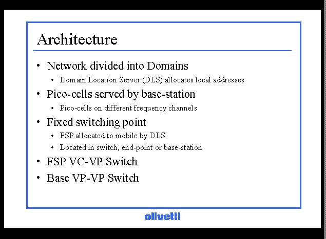
Architecture used to implement the mobile ATM system.
The combined wired/wireless network is divided into domains, which have both a physical and a logical interpretation.
Physically they represent an area of propagation in which it is expected that mobiles will move rapidly between base-stations. The small scale mobility.
Logically a domain represents an area which is covered by a single management entity - the domain location server. And in which the base-stations are considered to be owned by the same authority.
Movement within a domain is assumed to be transparent but it is conceivable that there may be billing or charging issues associated with moving between domains.
A domain is divided into a number of pico-cells each served by an access point or base-station. In the systems we are considering these are of the order of a few 10s of metres across. Pico-cells are coloured to with different frequencies to prevent adjacent cell interference so that within a cell the allocation of bandwidth can be managed to provide some QoS guarantees.
As mentioned the connections to a mobile are routed through a fixed switching point which is allocated to a mobile when it is registered within a domain by the DLS.
Virtual paths are established between the FSP and the appropriate base for each mobile.
The FSP can be located either in a switch, an ATM end-point or a base-station.
The most efficient implementation for the FSP is in a switch . In this case the location of the FSP can be chosen so that routing to the mobile is still fairly optimal and the switch is obviously designed to support the efficient relaying of cells.
The drawback with this approach is that there must be appropriate switches in a domain which run mobility support sufficient to support the FSP. Alternatively a server can be added which allows the FSP to run as an ATM end-point. Or the FSP can run within a base-station.
In this case the mobile system can run on switches which do not have mobility support. The FSP can be considered a Virtual Circuit to Virtual Path switch in which incoming virtual circuits on VPI0 are switched to the appropriate VPI for each mobile.
The base is a VP-VP switch, virtual circuits from a mobile are switched to the appropriate VPI used in the wireless link to distinguish the mobile. There is no VC translation required at the base.